


Part 3 - Create SubaruVanagon Wire Harness
(NOTE: These articles were written way back in 2010 - some processes have evolved so just keep that in mind)
A couple notes - This article was written many many years ago. For a slightly updated (but still years old) video series on the subject check out this YouTube series: Wiring Harness Conversion Playlist
If you decide this part of the project just isn't for you, have us complete the harness for you: Subaru Wiring Harness Conversion
Now, On to the article!!!
Re-Wiring the Subaru Wiring Harness
I am sure you have probably heard this step referred to as “Wire Hell”. We would like to propose that although wires are sometimes intimidating, this step in the conversion process does not have to be a stressful one. First of all, this step does not take as long as you would expect and if you work indoors you may not even break a sweat. For me, this is the relaxing and mentally engaging part of the conversion. Find a table, a room in your house, a cup of coffee, and breathe deep ….now release. Ok, seriously though, check out these easy steps and tell yourself “Wires are your friend”.
Differences between 1990-1994 and 1995+ Wiring Harness
The biggest difference between 90-94 and 95+ harnesses is OBD1 and OBD2 respectively. OBD stands for On-Board Diagnostics. This allows a technician, that’s you, to plug into the car’s computer and determine fault codes. In 1995+ Subaru cars switched from OBD1 to OBD2. So, you are faced with the question of which year Subaru engine to use. There are pros and cons to both systems, so you will have to decide for yourself. The following article uses a 90-94 wiring harness and engine for the example.
Time Necessary and Step Overview for Subaru Wire Harness Conversion
Obviously, the wire harness conversion will take everyone different amounts of time. If you have soldered wires before, then this should be a breeze and may only take you 16 hours total. The key word here is “total”. As a wiring newbie I would not attempt an entire wire harness conversion in two days. But if you are in a hurry, it can be done. The bulk of the work is in unwrapping and re-wrapping the wires. I decided to spread the work over the course of a week spending only a couple hours each day. I did not stress out and there was no “Hell”. So, my estimate for an entire harness conversion is that it may take you approximately 16 hours. If you don’t know what solder is, then it may take you a couple hours longer. Learning how to solder is easy as you will see in the video below.
Tools You May Need:
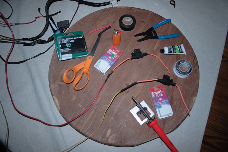
1. Scissors
2. Wire cutters
3. Electrical tape
4. Solder (make sure it is proper size for electronics)
5. Flux for solder
6. Soldering iron
7. Heat-shrink rubber tubing for electrical wires
8. Lighter
9. A 15 amp and 30 amp fuse holder and fuses (Local auto parts store)
Steps for 90-94 Legacy Wire Harness Conversion
Note: Refer to the attached document to see an ECU pinout for the 90-94 wire harness
Step 1: Unwrap the black protective plastic and tape from the harness
This is probably self explanatory, but don’t forget to use your scissors as they can give your fingers a break from tearing at the tape. Be careful not to cut any wires by accident.
Step 2: Label the required connectors and cut the unnecessary connectors
Label the following connectors (YOU NEED THESE)
Label the following connectors with masking tape and make sure you do not cut the wires attached to these components. After you have labeled the necessary connectors, you may now cut and remove the unnecessary connectors, but do not cut connectors that have wires going in one side and out the other at this time. Try to leave 2 inches of wire on the connectors so that if you mistakenly cut the wrong one, you can solder it back in place.


Double Check this list of necessary connectors and make sure you have each one labeled:
1. Ignition Relay (Brown)
2. Fuel Pump Relay (Green)
3. MAF (Mass Air Flow sensor, 5 Pin)
4. O2 Sensor
5. Engine connectors (2 square grey connectors in group)
6. Alternator (1 connector, and two large white leads)
7. Ignitor (6 Pin)
8. Rear engine (3 grey connectors)
9. ECU connectors (4 bright yellow)
10. Brown Double Diode
11. Green diagnostic connectors
12. Select Monitor and Black diagnostic connectors
13. Large grey connector with bolt through it (save for now)
Here are a few of the connectors we do not need:
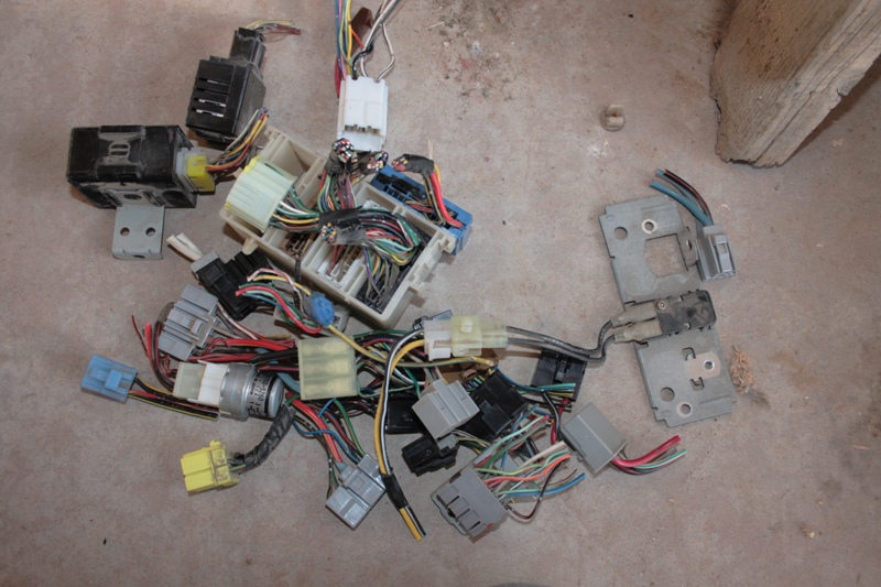
Step 3: Remove the loose wires
There is a great method to this madness. (This method is based on KEP’s instructions)
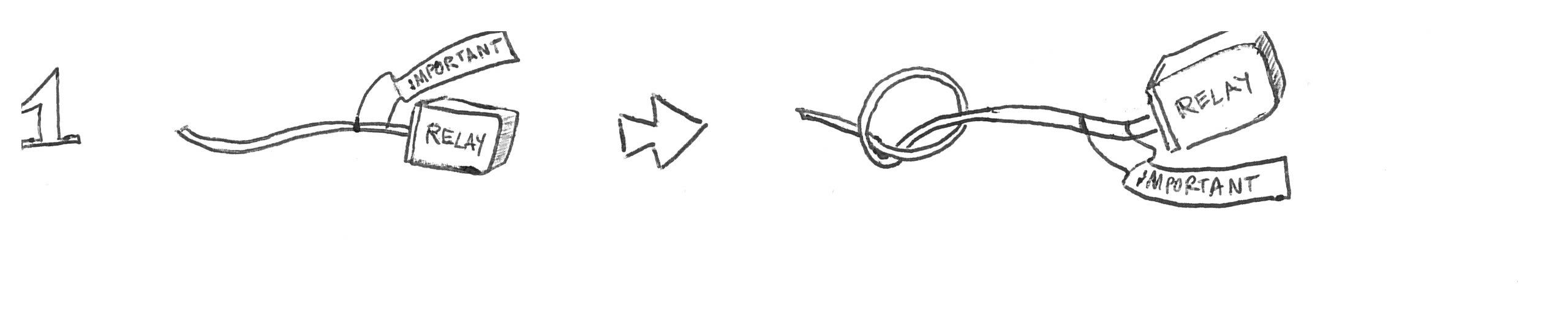
Now that you have quite a few cut wires, take a loose end of a cut wire and follow it until you find where it ends. There are only 4 possible endings:
- End at a necessary connector – Tie a knot at the loose end.
- End at a wire to wire direct splice- Cut one inch away from wire splice and continue to trace wire. Continue to follow actions 1-4.
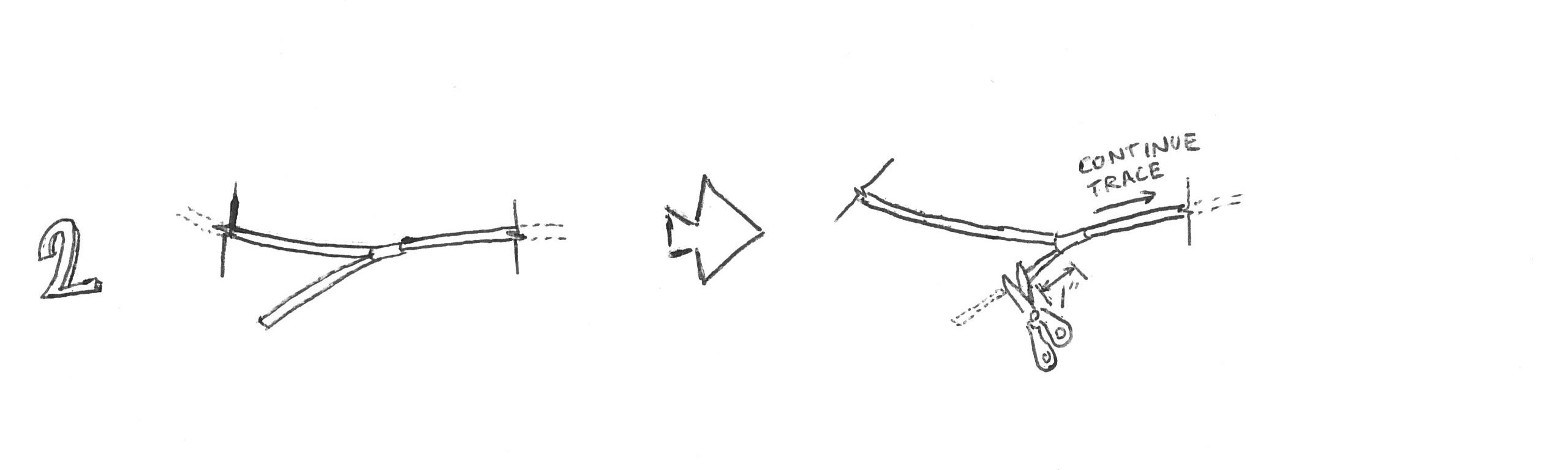
- End at unnecessary connector and travel through to other side- Cut wire at each side of connector and continue to trace wire. Continue actions 1-4.

- End at another cut end- The wire is loose, so remove it and save for future use.
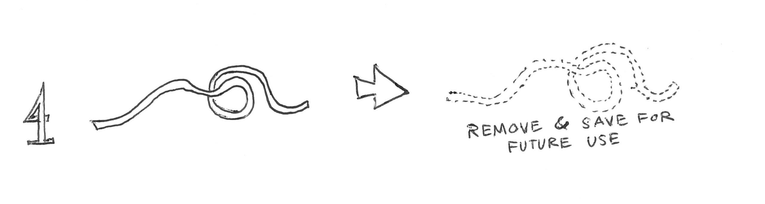
This step can go pretty quickly and I find it fun because you can quickly see the harness shrink in number of wires. Don’t get too carried away and cut the wrong wire.
Step 4: Trace Black/Red from fuel pump relay to blue connector. Cut at blue connector and label "To Fuel Pump"


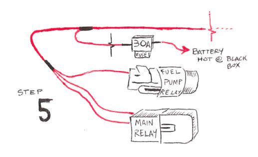
Step 5: Splice 3 large yellow wires from ignition & fuel pump relay to 30A fuse to battery hot
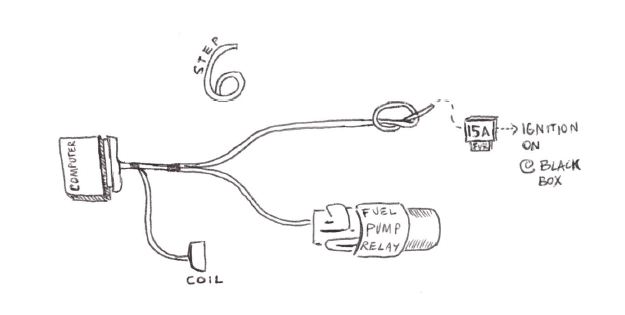
Step 6: Splice yellow wires from fuel pump relay, computer, and coil to ignition on through a 15A fuse


Step 7: What to do with the Alternator Wires?
The wiring that goes to the alternator does not need to tie-into the main harness but I chose to integrate it into the main harness. On the 90-94 harness there are 3 wires in the connector and a large white wire that goes to the post on the alternator. Pictured below is an illustration for a 95' alternator but the idea is very similar. The 3 wires at the connector: Large white to Battery +, yellow to Ignition ON, and Black/White to charge indicator light at the dash.

Summary:
The wiring harness can be a great joy if you don't let yourself bend to intimidation. This is a very rewarding part of the process and allows you to be intimate with the guts of the Subaru engine swap. You can find ECU pinouts here: https://busaru.com/services/resources